Camshaft Position Sensor Symptoms: Full Guide 2026
Camshaft position sensor symptoms include a check engine light, engine misfires, rough idle, hard starting, unexpected stalling, and in complete failure cases, a vehicle that will not start at all. Each of these drivability problems has a specific mechanical explanation rooted in how the sensor communicates camshaft angle data to the engine control module.
This sensor is smaller than your thumb and costs between $20 and $150 in most applications, yet its failure can make a vehicle act like it has a major engine problem. Understanding exactly why each symptom occurs, and how to distinguish cam sensor failure from the overlapping symptoms of a failed crankshaft position sensor, is the difference between an accurate diagnosis and an expensive misdirected repair.
This guide covers every drivability symptom with the specific electrical and mechanical reason behind it, the OBD-II fault codes each failure mode produces, how to differentiate camshaft from crankshaft sensor failure, and at what point a stalling or no-start vehicle becomes a road safety issue rather than a routine repair.
Camshaft Position Sensor Symptoms: The Full Symptom Picture
The complete symptom profile of a failing camshaft position sensor (CMP sensor) includes check engine light illumination, engine misfires, rough or erratic idle, difficulty starting (especially cold), intermittent stalling, reduced fuel economy, reduced power, and in complete failure, a no-start condition.
Not all symptoms appear simultaneously. The symptom pattern depends on the failure mode: a sensor with intermittent signal dropout produces different and often more confusing symptoms than one that has failed completely. An intermittently failing sensor may cause symptoms that come and go, sometimes disappearing entirely between episodes, which makes diagnosis harder than a clean complete failure.
The key symptoms in order of clinical diagnostic significance:
- Check engine light illuminated, with stored fault codes in the P0340 to P0344 range
- Engine misfires, particularly at idle or during acceleration, produced by incorrect injection timing
- Rough or unstable idle caused by erratic fuel injector sequencing
- Hard starting, especially on cold mornings, from loss of accurate cam-crank synchronization data
- Intermittent stalling at idle, in traffic, or immediately after start
- Reduced fuel economy from the ECM defaulting to a conservative, enriched fuel strategy
- Loss of power, particularly in VVT-equipped engines that lose cam phaser correction capability
- Complete no-start when signal loss is total and the ECM cannot calculate injection timing
Vehicles manufactured after 2005 with variable valve timing (VVT) systems tend to show more symptoms from the same degree of sensor degradation than older fixed-timing engines, because VVT systems depend on continuous cam sensor feedback for the cam phaser control loop.
What Is a Camshaft Position Sensor and What Does It Do
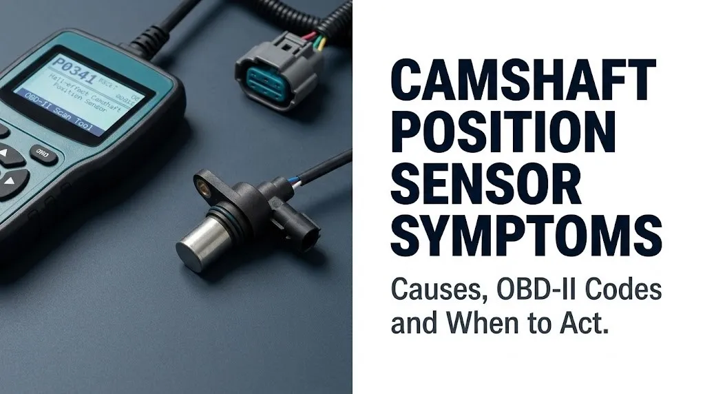
The camshaft position sensor is an electromagnetic or Hall-effect transducer that monitors the angular position of the camshaft in real time and transmits this data to the engine control module (ECM), which uses it to calculate the precise timing of fuel injection events and, in VVT-equipped engines, to control cam phaser actuator position.
Every four-stroke engine cycle requires precise coordination between piston position and valve position. The crankshaft position sensor (CKP) tells the ECM where the pistons are. The camshaft position sensor tells the ECM where the intake and exhaust valves are relative to those pistons. Together, these two data streams allow the ECM to determine which cylinder is on its compression stroke and ready for fuel injection and spark.
Think of the ECM as an orchestra conductor. The crankshaft sensor gives the beat (the rhythm), and the camshaft sensor identifies which instrument is playing (which cylinder is in which phase of its cycle). Without the camshaft sensor, the conductor knows the tempo but not which instrument to cue, forcing a guess that throws the whole performance off rhythm.
The sensor’s function in VVT systems adds a second responsibility: it provides closed-loop feedback for the cam phaser actuator. The ECM commands the cam phaser to advance or retard cam timing for fuel economy and power output, then reads the CMP sensor output to verify the phaser moved to the commanded position. Without accurate feedback, the ECM cannot correct phaser position, and VVT performance degrades entirely.
Quick Tip:
- Most modern passenger vehicles have at least one CMP sensor. DOHC engines have two per cylinder bank (one per camshaft), and a V-configuration DOHC engine may have four total.
- The sensor is typically located near the camshaft sprocket at the front or rear of the cylinder head.
- Vehicles with interference engines (where piston-to-valve contact is possible if timing is off) are particularly sensitive to cam sensor accuracy failures.
How a Camshaft Position Sensor Generates Its Signal
A Hall-effect camshaft position sensor generates its signal through magnetic field interruption: as the reluctor wheel (a toothed ring or disc mounted to the camshaft sprocket) rotates, each passing tooth interrupts the sensor’s magnetic field, producing a voltage transition from low (approximately 0V) to high (5V or 12V depending on system design) that the ECM reads as a digital square-wave pulse train.
The reluctor wheel tooth pattern is not uniform. It is specifically designed with gaps and teeth in a unique sequence that corresponds to each cylinder’s position in the firing order. The ECM counts tooth transitions and reads the gap positions to determine exact camshaft angle. This is not simply “how fast the cam is spinning” but a precise angular position calculation updated thousands of times per minute.
The ECM cross-references this cam position data against the crankshaft position sensor signal within a defined tolerance window, typically 10 to 15 degrees of crankshaft rotation. This cross-reference is called the cam-crank correlation check. If the cam sensor signal arrives outside this window, the ECM stores a range/performance fault code (P0341 or P0336) even if both sensors are generating signals, because the timing relationship between them is incorrect.
Older magnetoresistive cam sensors (used in some vehicles from the 1990s and early 2000s) generate an analog sine-wave signal rather than a digital square wave. These sensors are harder to test with a basic multimeter because their signal quality must be evaluated with an oscilloscope rather than a simple voltage check.
Signal failure modes and their diagnostic significance:
| Failure Mode | Signal Description | Typical Fault Code | Symptom Pattern |
|---|---|---|---|
| No signal output | Zero voltage, no transitions | P0340 or P0335 | Misfire, stall, potential no-start |
| Signal out of range | Signal present but wrong amplitude or timing | P0341 or P0336 | Rough idle, hard start, misfire |
| Circuit low | Signal line shorted to ground | P0342 or P0337 | No-start, check engine light |
| Circuit high | Signal line shorted to power | P0343 or P0338 | No-start, check engine light |
| Intermittent signal | Signal drops out randomly | P0344 or P0339 | Intermittent stall, intermittent misfire |
Check Engine Light and Camshaft Position Sensor Fault Codes
The malfunction indicator lamp (MIL), commonly called the check engine light, is the first and most consistent symptom of a camshaft position sensor problem, and it is almost always accompanied by one or more stored diagnostic trouble codes (DTCs) in the P0340 to P0344 range for camshaft sensor circuit faults.
These fault codes follow the OBD-II standard defined by SAE J1979 and ISO 15031, which are the international protocols governing on-board diagnostic systems in passenger vehicles sold in the United States since 1996. Every code in this range corresponds to a specific electrical fault in the cam sensor circuit:
- P0340: Camshaft Position Sensor Circuit, Bank 1. No signal received from the sensor. The ECM detects no voltage transitions on the signal circuit during cranking or operation.
- P0341: Camshaft Position Sensor Circuit Range/Performance, Bank 1. Signal is present but does not match expected timing relationship with the CKP sensor.
- P0342: Camshaft Position Sensor Circuit Low Input, Bank 1. Signal circuit voltage is continuously below threshold, indicating a short to ground.
- P0343: Camshaft Position Sensor Circuit High Input, Bank 1. Signal circuit voltage is continuously above threshold, indicating a short to power.
- P0344: Camshaft Position Sensor Circuit Intermittent, Bank 1. Signal drops out randomly, one of the hardest fault patterns to capture and confirm.
Bank 2 equivalents (P0345 through P0349) apply to the second camshaft bank in V-configuration engines with DOHC heads.
Retrieving these codes requires an OBD-II scan tool connected to the vehicle’s diagnostic port (the 16-pin OBD-II connector, standardized under SAE J1962). The freeze frame data stored with the code is equally important: it records engine speed (RPM), coolant temperature, load, and fuel trim values at the moment the fault was detected, giving a technician the exact operating conditions under which the failure occurred.
Older vehicles (pre-1996) do not use OBD-II and may require a manufacturer-specific scan tool to retrieve proprietary fault codes.
Engine Misfire and Rough Idle From a Bad Cam Sensor
Engine misfires caused by a failing camshaft position sensor occur because the ECM cannot accurately determine which cylinder is on its compression stroke, forcing it to inject fuel at incorrect intervals and in some cases causing fuel to be delivered during the exhaust stroke rather than the intake stroke.
Misfire is the symptom most vehicle owners notice most distinctly. It feels like a rhythmic stumble, jerk, or shudder under acceleration, at idle, or both. You may also notice the check engine light flashing rather than remaining steady. A flashing check engine light specifically indicates an active misfire severe enough to cause catalytic converter damage from raw fuel passing through the exhaust system. This is the one symptom that warrants stopping driving immediately.
Rough idle from cam sensor failure has a different cause. The ECM controls idle quality through precise fuel injector timing sequenced to each cylinder’s intake stroke. When cam position data is absent or erratic, the sequencing becomes approximate rather than precise. Each cylinder still receives fuel and spark, but not at the optimal moment. The result is a slightly uneven power contribution from each cylinder, which produces the characteristic rough, bouncing idle.
According to ASE (National Institute for Automotive Service Excellence) training materials for the Engine Performance (A8) certification series, cam sensor-induced misfires produce misfire counts distributed across multiple cylinders rather than a single-cylinder misfire, which is one diagnostic feature that distinguishes sensor-related misfires from mechanical misfires caused by a worn spark plug or bad ignition coil affecting only one cylinder.
Vehicles with higher mileage, particularly those over 100,000 miles, are more likely to experience cam sensor-related misfires from wiring harness connector corrosion than from sensor element failure, because the connector is exposed to engine heat and vibration cycles over its service life.
Key Takeaway: A flashing check engine light combined with a rough idle or misfire shudder is not a “drive it and see” situation: pull over when safe and have the vehicle towed, because active misfires can destroy a catalytic converter within minutes of onset.
Hard Starting and No-Start Symptoms From Cam Sensor Failure
A failing camshaft position sensor causes hard starting because the ECM must use the camshaft signal to determine which cylinder is approaching top dead center (TDC) on the compression stroke during cranking, and without this data, it cannot deliver the first injection pulse with confidence until the cam-crank relationship is established through multiple crankshaft revolutions.
In a healthy engine, starting occurs in two to three crankshaft revolutions because the ECM immediately identifies cylinder position from both the CKP and CMP signals simultaneously. With a failing CMP sensor, the ECM may take six to ten crankshaft revolutions or more to establish cylinder position from CKP data alone, producing the characteristic extended cranking time before the engine fires. The driver experiences this as “the engine cranks and cranks before it starts.”
A complete no-start from cam sensor failure is less common than hard starting, because most modern ECMs have a fallback strategy that uses CKP data alone to estimate cylinder position. However, some engine management systems, particularly certain Ford, Chrysler, and early 2000s GM applications, treat the CMP signal as the primary sequential injection trigger and will not initiate sequential injection without it. In these systems, a complete cam sensor signal loss causes a no-start condition rather than degraded starting.
Cold-start conditions make cam sensor hard-starting symptoms worse for a specific reason: the ECM requires a richer fuel mixture during cold start, calculated in part from accurate injection timing data. Without cam position confirmation, the cold-start enrichment strategy is degraded, making the engine harder to fire on cold mornings.
To distinguish cam sensor hard starting from other causes:
- Connect an OBD-II scan tool before attempting diagnosis.
- Retrieve stored fault codes. P0340 or P0344 with a hard-start complaint points directly to the cam sensor circuit.
- Note whether the vehicle starts after extended cranking (cam sensor fault) versus never starting at all (more consistent with CKP failure or fuel system failure).
- Check whether starting improves when the engine is warm. Cam sensor hard-starting is often worst when cold and improves once the engine reaches operating temperature.
- Review live data PID for “Cam Position” or “CMP Signal” during cranking to see whether the ECM is receiving a signal.
Engine Stalling Symptoms From a Failing Camshaft Sensor
Engine stalling caused by a camshaft position sensor fault occurs when the sensor’s output signal drops out suddenly during operation, removing the cylinder position reference from the ECM and causing the engine management system to interrupt fuel injection momentarily or permanently until the signal is re-established.
Stalling from a cam sensor fault has a characteristic pattern. The engine typically stalls without warning: no preceding power loss or rough running, just an abrupt shutdown. This is because intermittent signal dropout (the P0344 failure mode) is a binary event. The signal is present, then it is absent for a fraction of a second, which is long enough for the ECM to halt injection on one or more cylinders. The result is a momentary stumble or a complete stall.
The physical cause of intermittent signal dropout is often the wiring harness rather than the sensor element itself. Hairline cracks in the signal wire insulation, corroded connector terminals, or a loose connector pin can create intermittent open circuits that the sensor circuit sees as signal loss. These wiring faults are temperature-sensitive: a crack that creates no circuit break at room temperature may open fully when the engine reaches operating temperature and the wiring expands, which is why intermittent cam sensor stalling is often more prevalent once the engine is warm.
Stalling that occurs specifically during deceleration or at idle in stop-and-go traffic has an additional mechanism. At low RPM and load, the ECM relies more heavily on precise cam timing data to maintain stable idle, because the injection timing window is tighter at low cylinder speed. A sensor that is marginally functional at cruising speed may fail to provide adequate signal resolution at idle, causing the engine to stall precisely when coming to a stop.
Vehicles operated in regions with significant road salt exposure (affecting the wiring harness and connector terminals) or in high-heat engine bay environments (V8 trucks, older turbocharged applications) show higher rates of wiring-harness-induced cam sensor stalling faults compared to those in mild climates.
Poor Fuel Economy and Performance Loss From Cam Sensor Failure
A failing camshaft position sensor reduces fuel economy because the ECM, unable to verify accurate cam position, defaults to a conservative fuel injection strategy that enriches the air-fuel mixture beyond the stoichiometric ratio of 14.7:1 to ensure adequate combustion under the degraded timing condition.
This is a protective default. The ECM would rather run slightly rich (more fuel than ideal) than risk a cylinder running lean, which can cause combustion temperatures high enough to damage pistons or exhaust valves. The trade-off is measurable: drivers with a failing cam sensor often notice a 10 to 20 percent reduction in fuel economy before any other symptom becomes obvious, particularly on vehicles with direct injection engines where injection timing precision has the most direct effect on combustion efficiency.
Performance loss follows the same logic. Optimal engine power requires fuel injection precisely at the beginning of the intake stroke and ignition precisely at the optimum advance angle for the current load and RPM. When the ECM cannot verify cam position, it retards ignition timing as a precaution, reducing combustion pressure and therefore reducing torque output. The vehicle may feel sluggish, particularly during acceleration from a stop or when climbing a grade.
The Bosch Automotive Handbook (14th Edition) states that injection timing accuracy in modern direct injection engines requires cam position resolution of less than 1 degree of crankshaft rotation for optimal combustion efficiency. A cam sensor producing a degraded or marginally inaccurate signal can therefore produce measurable fuel economy losses even before drivability symptoms become obvious to the driver.
Vehicles with continuously variable transmissions (CVTs) may mask performance loss symptoms because the transmission’s RPM management compensates partially for reduced torque output, making the performance degradation feel less dramatic than in a vehicle with a conventional automatic or manual transmission.
Key Takeaway: A 10 to 15 percent reduction in fuel economy with no other obvious cause, particularly in a direct injection vehicle with high mileage, warrants an OBD-II scan for cam sensor fault codes even before misfires or stalling develop.
Symptoms of a Bad Crankshaft Position Sensor
The symptoms of a bad crankshaft position sensor (CKP sensor) include check engine light illumination with fault codes in the P0335 to P0339 range, engine stalling, hard starting, misfires, and in complete failure, an engine that will not start at all and cannot be started regardless of cranking duration.
The CKP sensor performs the same Hall-effect or variable reluctance signal generation as the cam sensor, but its reluctor wheel (typically a 60-minus-2 tooth wheel mounted to the crankshaft) provides the primary timing reference for the entire engine management system. In most modern engine management strategies, the CKP signal is the master timing input and the CMP signal is the secondary reference used to confirm cylinder identification.
Because the CKP provides the primary timing reference, its failure is typically more immediately disabling than cam sensor failure. Most engine management systems cannot calculate injection timing or ignition timing at all without a valid CKP signal, which is why complete CKP failure almost always produces a no-start condition, while complete CMP failure often allows the engine to start and run in a degraded mode.
Crankshaft position sensor fault codes by circuit fault type:
| Fault Code | Circuit Fault | Typical Symptom |
|---|---|---|
| P0335 | CKP Circuit, No Signal | No-start, engine cranks but will not fire |
| P0336 | CKP Signal Range/Performance | Stall, misfire, hard start |
| P0337 | CKP Circuit Low Input | No-start, check engine light |
| P0338 | CKP Circuit High Input | No-start, check engine light |
| P0339 | CKP Signal Intermittent | Intermittent stall, random misfire |
High-mileage vehicles are more likely to develop CKP sensor failure from reluctor wheel damage (caused by a loose crankshaft reluctor ring in some applications), while lower-mileage vehicles more often develop CKP faults from wiring harness connector corrosion, particularly at the bottom of the engine where road moisture exposure is highest.
Cam Sensor Symptoms vs. Crankshaft Position Sensor Symptoms
The most reliable way to distinguish camshaft position sensor failure from crankshaft position sensor failure is by whether the vehicle can start and run at all, because CKP failure typically produces a complete no-start while CMP failure more often allows degraded operation, and by the specific OBD-II fault codes (P034x for cam, P033x for crank) stored in the ECM.
This distinction matters practically because the sensors, while functionally related, are located in different positions on the engine and require different access procedures and replacement costs. Diagnosing the wrong sensor wastes both time and money.
Overlapping symptoms that both sensors produce: check engine light, engine misfire, rough idle, stalling, and hard starting. These shared symptoms exist because both sensors feed the same ECM timing calculation, so both types of failure disrupt the same downstream functions.
| Symptom / Feature | CMP Sensor Failure | CKP Sensor Failure |
|---|---|---|
| Check engine light | Yes, P0340-P0344 | Yes, P0335-P0339 |
| No-start condition | Possible, not typical | Very common |
| Starts after extended cranking | Yes, often | Rarely |
| Engine runs but misfires | Yes | Less often |
| Stalling while running | Yes, especially intermittent | Yes |
| VVT performance loss | Yes (cam phaser loses feedback) | No direct VVT effect |
| Sensor location | Cylinder head, near cam sprocket | Transmission bell housing or block, near crank |
| Fault code range | P0340-P0349 | P0335-P0339 |
| Will it run in limp mode | Often yes | Rarely |
The practical diagnostic step: retrieve OBD-II fault codes first. The specific code range (P034x vs. P033x) tells you which sensor circuit has the fault before any physical inspection begins. If both code ranges are present simultaneously, the cam-crank correlation fault (P0016, P0017, P0018, P0019) may also appear, indicating that the timing relationship between the two sensors is incorrect, which can point to a stretched timing chain or worn cam phaser rather than a sensor failure.
Limp Mode and VVT Symptoms From Camshaft Sensor Failure
Limp-home mode (also called reduced power mode or fail-safe mode) is the ECM’s protective response to a confirmed cam sensor fault, in which the engine management system disables variable valve timing correction, limits maximum engine RPM, and in some applications restricts throttle opening to prevent engine damage while allowing the vehicle to reach a service location.
Think of limp mode like a hospital’s emergency transport protocol. The goal is not optimal performance but safe arrival. The ECM, recognizing that it cannot trust the cam position data, removes the systems that most depend on it (VVT correction, optimal injection timing) and runs the engine on conservative fixed parameters. The vehicle will typically accelerate slowly, have a noticeable top speed limitation, and the check engine light will remain continuously illuminated.
Variable valve timing systems deserve specific attention because their failure presentation is distinct. In VVT-equipped engines, the cam sensor does not only inform injection timing. It also provides the closed-loop feedback for the cam phaser actuator, which adjusts cam timing in response to throttle position, RPM, and load. When the cam sensor fails in a VVT system, the ECM loses the ability to verify whether the cam phaser has moved to its commanded position. The result is a stuck-at-park cam phaser, which produces:
- Loss of low-RPM torque (because VVT advance at low RPM is designed to improve low-end power)
- Reduced fuel economy at highway speed (because VVT retard at high RPM reduces pumping losses, and this is lost)
- Increased hydrocarbon (HC) emissions from incomplete combustion timing optimization
- In some Ford VCT and Toyota VVT-i applications, a secondary fault code for the cam phaser circuit (P0011, P0012, P0021, P0022 — cam timing over-advanced or over-retarded) stored alongside the cam sensor fault code
According to the Mitchell1 ProDemand service information database, cam phaser-related fault codes stored alongside CMP sensor circuit codes indicate that the diagnostic should include inspection of both the sensor and the oil control valve (OCV) that controls cam phaser hydraulic pressure, as OCV restriction from oil sludge can mimic cam sensor failure symptoms in VVT systems.
Intermittent vs. Complete Camshaft Position Sensor Failure Symptoms
Intermittent camshaft position sensor failure is the most diagnostically challenging presentation because the symptoms appear randomly, may disappear entirely between episodes, and can persist for weeks or months before the fault becomes consistent enough to store a permanent fault code rather than a pending code.
Complete cam sensor failure produces consistent, repeatable symptoms: the vehicle always has trouble starting, always has a rough idle, or simply will not start at all. A scan tool will show a confirmed (not pending) fault code, and the live data PID for cam sensor signal will show zero or no transitions. This is a straightforward diagnosis.
Intermittent failure is different. The sensor works correctly most of the time and fails only under specific conditions: after the engine reaches operating temperature (heat-induced wire expansion breaking a hairline crack), after driving over rough roads (vibration-induced connector pin movement), or after rain exposure (moisture-induced connector corrosion creating momentary resistance spikes). Between episodes, the vehicle runs perfectly and may show no fault codes at all if the ECM has cleared the pending code before it was read.
To document an intermittent cam sensor fault effectively:
- Connect an OBD-II scan tool that supports continuous live data recording (a data logger function).
- Set up a live data stream monitoring the cam sensor signal PID, RPM, and misfire count simultaneously.
- Drive the vehicle under the conditions that produce the symptom (highway speed, after warmup, etc.).
- Review the recorded data for the moment the symptom occurred to see whether cam sensor signal dropped to zero or showed aberrant values at that instant.
- Inspect the wiring harness connector physically: look for pin corrosion (green or white oxidation on terminals), loose terminal fit, cracked wire insulation near the connector or where the harness contacts engine components, and evidence of rodent damage to wire insulation.
- Perform a wiggle test on the harness connector while monitoring live data: a fault that appears only when the connector is wiggled confirms a wiring rather than sensor fault.
Intermittent faults caused by wiring harness issues are more prevalent in vehicles operating in high-temperature engine bays (turbocharged engines, tightly packaged four-cylinder engines) and in vehicles with over 120,000 miles where original factory wiring insulation has experienced significant thermal cycling.
Key Takeaway: If your scan tool shows only a pending (not confirmed) cam sensor code that clears itself, the fault is almost certainly intermittent and most likely wiring-harness-related rather than a sensor element failure, which changes both the diagnostic approach and the repair.
DOHC and Multi-Cam Engine Camshaft Sensor Symptoms
Dual overhead camshaft (DOHC) engines require one camshaft position sensor per camshaft, meaning a four-cylinder DOHC engine has two CMP sensors, a V6 DOHC has four, and a V8 DOHC has four or more, and the symptom profile depends specifically on which sensor is failing and whether it controls the intake cam, the exhaust cam, or both.
In a DOHC VVT engine, the intake camshaft sensor and exhaust camshaft sensor serve different functions. The intake cam sensor typically feeds the primary cylinder identification signal used for sequential injection. The exhaust cam sensor primarily provides feedback for exhaust cam phaser control. When the intake cam sensor fails in a DOHC engine, the symptoms are similar to a SOHC cam sensor failure: hard starting, misfire, rough idle. When the exhaust cam sensor fails, the primary injection system may remain functional, but exhaust valve timing correction is lost, producing reduced fuel economy and increased emissions with less dramatic drivability symptoms.
Bank-specific failure in V-configuration DOHC engines adds another layer. A P0345 code (CMP Bank 2 Sensor A) indicates the cam sensor serving the second cylinder bank has failed. The symptom pattern will be a misfire predominantly affecting Bank 2 cylinders (cylinders 2, 4, 6 in a typical V6), because injection sequencing for those cylinders has lost its timing reference while Bank 1 cylinders continue with accurate cam data.
According to the ALLDATA repair database, DOHC engines from several manufacturers, including BMW, Audi, and certain Honda applications, have documented technical service bulletins (TSBs) for cam sensor connector seal failures that allow oil contamination to reach the sensor element, producing signal degradation that mimics intermittent sensor failure but is actually connector-level contamination. In these cases, cleaning and resealing the connector resolves the symptom without sensor replacement.
Diagnosis in DOHC applications requires knowing which specific sensor (intake vs. exhaust, Bank 1 vs. Bank 2) corresponds to which fault code, which is OEM-specific and must be verified in OEM wiring diagrams rather than assumed from generic fault code descriptions.
How to Test a Camshaft Position Sensor
Testing a camshaft position sensor begins with OBD-II fault code retrieval, proceeds through a reference voltage and ground circuit check with a digital multimeter, and is confirmed with oscilloscope waveform capture or live data PID monitoring during cranking or operation.
This is not a single-step test. A sensor can pass a static resistance test and still fail dynamically during engine operation. Each test answers a different diagnostic question:
To perform a systematic camshaft position sensor test:
- Retrieve OBD-II fault codes with a scan tool. Record both confirmed and pending codes. Note the freeze frame data showing operating conditions when the fault occurred.
- With the ignition on and engine off, back-probe the sensor connector (do not unplug it) and measure reference voltage on the 5V supply wire. This should read 4.5V to 5.5V. A reading below 4V suggests a fault in the ECM reference voltage circuit, not necessarily the sensor.
- Measure ground circuit resistance between the sensor ground wire pin and a known chassis ground. This should be below 0.5 ohms. Higher resistance indicates a degraded ground connection that will corrupt the signal.
- For a static sensor resistance test (applicable to magnetoresistive/variable reluctance sensors only, not Hall-effect): unplug the sensor and measure resistance across the signal terminals. Compare to OEM specification (typically 200 to 900 ohms depending on design). Hall-effect sensors cannot be meaningfully tested this way.
- Connect an oscilloscope to the signal wire and crank the engine (or run it at idle). The output should show a clean, consistent digital square wave (Hall-effect) or sine wave (variable reluctance) with transitions matching the reluctor wheel tooth pattern. Missing teeth, irregular amplitude, or signal dropout during the test confirms sensor element failure.
- If oscilloscope equipment is unavailable, monitor the cam sensor PID in live data on the scan tool while cranking. A functional sensor will show RPM-synchronized signal activity. A failed sensor will show zero or a frozen value.
A basic multimeter is insufficient for confirming Hall-effect sensor function during operation. An oscilloscope or a scan tool with live data capability is required for a definitive test.
Can You Drive With a Bad Camshaft Position Sensor
You can drive with a bad camshaft position sensor under limited conditions: if the vehicle starts, runs without stalling, and the check engine light is on but not flashing, you may be able to drive it a short distance to a repair facility, but driving with an intermittently stalling or misfiring vehicle on highways or in heavy traffic is a road safety risk.
The specific conditions that make driving unsafe:
- Check engine light is flashing: this indicates an active misfire severe enough to damage the catalytic converter. Every minute of driving with a flashing check engine light risks destroying a catalytic converter that costs $500 to $2,500 to replace.
- The vehicle stalls without warning: unexpected engine shutdown at any speed removes power steering assistance and reduces braking effectiveness, creating a road safety hazard.
- The vehicle stalls and will not restart: you are now stranded, requiring roadside assistance regardless.
- You are on a highway or in a location where stalling is dangerous: even a 30-second engine shutdown at 65 mph is a collision risk.
If your vehicle starts, runs, and does not stall or misfire, you have a window for a planned drive to a shop. Keep it short, avoid highways, and have the shop’s phone number ready.
Prolonged driving with a confirmed cam sensor fault causes secondary damage:
- Catalytic converter damage from repeated misfires allowing raw fuel into the exhaust
- Increased carbon buildup on injectors and intake valves from non-stoichiometric combustion
- In VVT engines, potential cam phaser wear from operating continuously at a fixed timing angle without the correction it is designed for
Vehicles with turbochargers are particularly vulnerable to secondary damage from cam sensor failure because turbo boost control often depends on engine load calculations that include cam timing data, and degraded calculations can cause overboost conditions in some applications.
When Camshaft Sensor Symptoms Need Immediate Professional Diagnosis
Camshaft position sensor symptoms require immediate professional diagnosis by an ASE-certified automotive technician when the vehicle is stalling unpredictably at any road speed, when the check engine light is flashing during operation, when the vehicle will not start, or when stored fault codes include both cam sensor codes and cam phaser codes simultaneously.
An ASE-certified technician with engine performance (A8) certification has the diagnostic equipment and training to perform the oscilloscope waveform testing, live data analysis, and wiring harness inspection that a definitive cam sensor diagnosis requires. A basic OBD-II code reader from a parts store retrieves the fault code but cannot confirm whether the fault is in the sensor element, the wiring harness, the connector, or the ECM reference voltage circuit.
When fault codes include both cam sensor codes (P0340-P0344) and cam phaser timing codes (P0011, P0012, P0021, P0022) simultaneously, the diagnosis requires a master automotive technician or a dealership diagnostic technician with access to OEM-level scan tool software. These combined code sets may indicate a stretched timing chain, worn cam phaser, or restricted oil control valve rather than a failed sensor, and misdiagnosis leads to sensor replacement that does not resolve the underlying condition.
Call roadside assistance immediately if the vehicle stalls on a highway or in a location where exiting the vehicle is unsafe. Do not attempt to restart a stalled vehicle while still in a travel lane. Activate hazard lights, coast to a safe stopping location if possible, and wait for assistance outside the vehicle if highway traffic is present.
| Symptom Severity | Driving Safety | Recommended Action |
|---|---|---|
| Check engine light on, no other symptoms | Acceptable for short distance | Schedule diagnosis within 48 to 72 hours |
| Rough idle, minor misfire at idle | Marginal | Drive to shop same day, avoid highways |
| Flashing check engine light | Unsafe for extended driving | Stop when safe, tow to shop |
| Intermittent stalling at idle | Unsafe for highway use | Drive to shop at low speed same day |
| Stalling at highway speed | Unsafe, road hazard | Pull over immediately, call roadside assistance |
| No-start | Vehicle cannot be driven | Call roadside assistance for tow |
Frequently Asked Questions About Camshaft Position Sensor Symptoms
What are the most common symptoms of a bad camshaft position sensor?
The most common camshaft position sensor symptoms are a check engine light with stored fault codes in the P0340 to P0344 range, engine misfires, rough idle, hard starting (especially cold), and intermittent stalling.
In VVT-equipped vehicles, additional symptoms include reduced fuel economy, loss of low-RPM torque, and the engine entering limp-home mode with limited RPM and throttle response.
A flashing check engine light during a misfire episode is the most urgent presentation and warrants stopping driving immediately to prevent catalytic converter damage.
Can I drive my car with a bad camshaft position sensor?
You can drive short distances to a repair shop if the vehicle starts, runs without stalling, and the check engine light is on but not flashing.
Driving is unsafe if the check engine light is flashing (indicating active catalytic-converter-damaging misfires), if the vehicle is stalling unpredictably, or if you are on a highway where stalling would create a collision risk.
Extended driving with a confirmed cam sensor fault causes secondary damage including catalytic converter damage and cam phaser wear in VVT-equipped engines.
What is the difference between a bad cam sensor and a bad crank sensor?
A bad camshaft position sensor typically allows the engine to start and run in a degraded mode, while a bad crankshaft position sensor more commonly causes a complete no-start condition because the CKP provides the primary timing reference in most engine management systems.
Both sensors produce check engine lights, misfires, and stalling, but the specific fault codes differ: cam sensor faults store P0340-P0344 and crank sensor faults store P0335-P0339.
Retrieving and identifying the specific OBD-II fault code is the fastest and most reliable way to distinguish between the two sensor failures before any physical inspection.
What OBD-II codes does a bad camshaft position sensor trigger?
A bad camshaft position sensor triggers fault codes P0340 through P0344, plus Bank 2 equivalents P0345 through P0349 in V-configuration DOHC engines.
P0340 indicates no signal, P0341 indicates signal out of range relative to the crankshaft sensor, P0342 indicates a circuit low (ground short) fault, P0343 indicates a circuit high (power short) fault, and P0344 indicates an intermittent signal dropout.
In VVT-equipped engines, cam phaser timing codes P0011 or P0012 may appear alongside the cam sensor circuit codes when sensor failure has prevented cam phaser correction from functioning.
Will a bad camshaft position sensor cause a no-start condition?
A bad camshaft position sensor can cause a no-start condition, but it is more likely to cause hard starting (extended cranking before the engine fires) rather than a complete inability to start, because most modern ECMs have a fallback strategy that uses crankshaft position data alone to estimate cylinder position.
Some vehicle-specific engine management systems, particularly certain Ford, Chrysler, and early 2000s GM applications, treat the cam sensor as a required input for sequential injection and will not allow the engine to start without a valid cam signal.
A complete no-start with a fault code of P0340 (no cam signal) in these applications requires the vehicle to be towed rather than driven to a repair facility.
How do I test a camshaft position sensor at home?
Connect an OBD-II scan tool to retrieve the specific fault code and freeze frame data first, then use a digital multimeter to verify the 5V reference voltage and ground circuit resistance at the sensor connector while the ignition is on.
If you have access to a scan tool with live data capability, monitor the cam sensor signal PID while cranking the engine: a functional sensor will show activity synchronized with engine cranking, while a failed sensor will show zero or a static value.
Definitive confirmation of sensor element failure (versus wiring or connector failure) requires an oscilloscope to capture the square-wave signal pattern during operation, a tool that basic multimeters cannot replicate.
Taking the Next Step on Cam Sensor Diagnosis
The practical path forward is straightforward. Pull the OBD-II codes first, before replacing anything. The specific code in the P034x range tells you which sensor circuit has a fault. The freeze frame data tells you the operating conditions when it failed. Those two pieces of information together are worth more than any symptom list.
If the code is P0344 (intermittent), start with the wiring harness and connector before replacing the sensor. Connector corrosion and hairline wire cracks cause more intermittent cam sensor faults than failed sensor elements, and a connector cleaning or repair is faster and cheaper than a sensor replacement that does not fix the problem.
When the check engine light is flashing, the vehicle is stalling unpredictably, or stored codes include both cam sensor and cam phaser timing codes simultaneously, schedule diagnosis with an ASE-certified automotive technician with engine performance credentials, and bring your code readout and symptom timeline to that appointment.